
HIRSCHMANN MACH1040 family Full Gigabit Industrial Ethernet Ruggedized Switch
Safety regulations and installation environment requirements
(1) Personnel qualification requirements
Only "qualified personnel" are allowed to operate the equipment. Qualified personnel must meet the following requirements: have received professional training, possess knowledge of safety technical standards related to circuit grounding and identification; Understand potential hazards in the workplace; Master risk prevention measures; Regularly receive retraining.
(2) Mandatory requirements for installation environment
Installation location: It can only be installed in switch cabinets or restricted access areas, and is exclusively accessible to maintenance personnel; Prohibited for use as a desktop device.
Installation method adaptation:
19 inch cabinet installation: sliding/mounting rails are required to support the weight of the equipment and ensure easy cable access; At least one rack space (about 5cm) should be reserved above and below the device for heat dissipation.
Vertical installation on the wall: It must be installed inside a fire-resistant enclosure that complies with IEC/EN 62368-1 standards to avoid the risk of fire.
Environmental parameter threshold:
Temperature: Standard (S) 0 ° C~+60 ° C (+32 ° F~+140 ° F); Expansion type (T/E) -40 ° C~+70 ° C (-40 ° F~+158 ° F), with additional conformal coating for E-type; Storage temperature -40 ° C~+85 ° C.
Humidity: 5%~95% (non condensing state).
Air pressure: up to 2000 meters (795 hPa), higher altitudes require prior consultation.
Pollution level: not exceeding level 2.
Special requirements for hazardous environments (Class 1, Division 2):
Only use models labeled "FOR USE IN CLASS I, DIVISION 2 HAZARDOUS LOCATION".
When using the USB port, it is necessary to install a tool to lock the casing to prevent accidental operation.
It is prohibited to disassemble or replace equipment when it is in a charged state, unless it is confirmed that there is no concentration of flammable gases in the area.
Do not replace any components as it may affect explosion-proof compatibility.
Signal contacts must comply with electrical parameters (Vmax 30V, Imax 90mA, Ci 50pF, Li 2 μ H), cable length must be calculated based on capacitance/inductance parameters (default 60pF/ft, 0.2uH/ft), and wiring must follow NEC NFPA 70 Article 501 standard.
(3) Electrical safety regulations
Power supply safety:
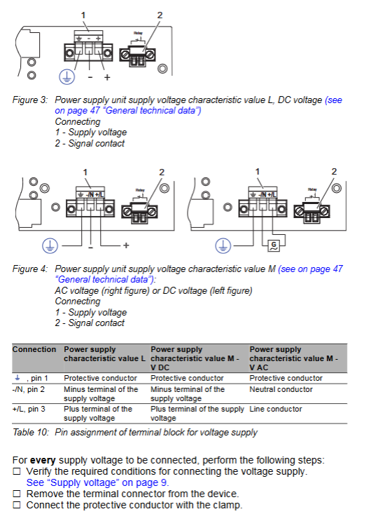
The power supply voltage must be consistent with the equipment nameplate, L-type (24-48VDC), M-type (100-240VAC/110-250VDC), with a voltage range including maximum tolerance (L-type 18-60VDC, M-type 90-265VAC/77-300VDC).
The power cord needs to use copper wire with a cross-sectional area of not less than 1mm ² (North American AWG16); The cross-sectional area of the protective conductor shall not be less than the power supply wire and shall not be less than 1.0mm ² (AWG16).
The power supply should be equipped with easily accessible disconnect devices (such as switches, plugs) and clearly labeled; The outer conductor of AC power supply or the positive conductor of DC power supply should be equipped with fuses (L-type 6.3A slow melting, M-type 2.5A slow melting), and double fuses are required when the neutral/negative wire is not grounded.
Grounding requirements:
The device is grounded through an independent grounding screw on the back, and the grounding operation must take priority over other cable connections; The grounding cable needs to be operated last when disconnecting.
The shielded grounding wire of the twisted pair cable should be connected to the front panel of the equipment, and the risk of short circuit should be avoided during connection.
Cable and connection safety:
The cable needs to be designed for stress relief to avoid twisting, poor contact, or interruption caused by mechanical stress; Follow the requirements of sections 522.6, 522.7, and 522.13 of DIN VDE 0100-520:2013-06 standard.
At least 10cm of space should be reserved in front of the equipment ventilation duct to ensure heat dissipation; Do not insert sharp objects into equipment or wiring terminals, and do not touch live terminals.
When the device is running or just turned off, the casing may be hot. Do not touch it to avoid burns.
Complete installation process
(1) Preparation before installation
Packaging content inspection: Confirm that it includes 1 device, 2 pre installed brackets and fixing screws, 1-2 3-core power supply terminal blocks (according to model), 1-2 2-core signal contact terminal blocks (according to model), and 1 safety and general information sheet; Check all components for any transportation damage.
Tools and accessories preparation: Prepare suitable screwdrivers, torque wrenches (power terminal 0.51Nm, signal contact terminal 0.34Nm), cables that meet specifications (power line, ground wire, data line), and optional HIRSCHMANN compatible SFP optical modules.
Installation location confirmation: Ensure that the installation location meets environmental parameters, space requirements, and power supply conditions match the equipment.
(2) Core installation steps
1. Optional steps: Install SFP optical module
Remove the SFP optical module from the shipping packaging and remove the protective cap.
- OMRON
- ABB
- General Electric
- EMERSON
- Honeywell
- HIMA
- ALSTOM
- Rolls-Royce
- MOTOROLA
- Rockwell
- Siemens
- Woodward
- YOKOGAWA
- FOXBORO
- KOLLMORGEN
- MOOG
- KB
- YAMAHA
- BENDER
- TEKTRONIX
- Westinghouse
- AMAT
- AB
- XYCOM
- Yaskawa
- B&R
- Schneider
- KONGSBERG
- NI
- WATLOW
- ProSoft
- SEW
- ADVANCED
- Reliance
- TRICONEX
- METSO
- MAN
- Advantest
- STUDER
- DANAHER MOTION
- Bently
- Galil
- EATON
- MOLEX
- DEIF
- B&W
- ZYGO
- Aerotech
- DANFOSS
- Beijer
- Moxa
- Rexroth
- Johnson
- WAGO
- TOSHIBA
- BMCM
- SMC
- HITACHI
- HIRSCHMANN
- Application field
- XP POWER
- CTI
- TRICON
- STOBER
- Thinklogical
- Horner Automation
- Meggitt
- Fanuc
- Baldor
- SHINKAWA
- Other Brands
- UniOP
- KUKA
- Iba
- Beckhoff
-
 Basler DECS-200-2L Digital Excitation Control
 -
 Basler BE1-47N Voltage Phase Sequence Relay
 -
 Basler AEC63-7 Analog Excitation Controller 220-277V
 -
 Basler BE1-50/51B-107 Overcurrent Relay
 -
 Basler Electric BE1‑32R BE1‑E1P‑BON0F Protective Relay
 -
 Basler BE1-25 Solid State Time Overcurrent Relay M1EA6PA5S1F
 -
 Basler MVC 232 Manual Voltage Control Module 90 37000 103 60VAC 55VDC
 -
 Basler RAL6144-16GM Racer GigE Line Scan Camera
 -
 Basler SSR 63-12 Static Voltage Regulator
 -
 Basler BE1-51A Overcurrent Relay
 -
 Basler BE1-87T Solid State Protective Relay
 -
 Basler SR4A2B01B3A Static Voltage Regulator
 -
 Basler SSR 32-12 Static Voltage Regulator
 -
 Basler TRR00696 Transformer 1KVA 115V
 -
 Basler DECS-100-B15 AVR Replacement
 -
Basler BE1-27 Under-Voltage Relay
-
 Basler ACA2000-50GM Interface Module
 -
 Basler AEC63-7 Analog Excitation Controller
 -
 Basler PRS 250 Veri-Sync Relay
 -
 Basler SR4A-2B15B3A Static Voltage Regulator
 -
Basler BE1-32R Power Relay
-
Basler SR8A-2B06B3E Static Voltage Regulator
-
Basler BE1-81 O/U Frequency Relay
-
 Basler BE1-51A-K2E-W6M-B1N0F Overcurrent Relay
 -
Basler BE1-851 Overcurrent Relay G3A1S1 – 48-125V AC/DC
-
 Basler BEI-51 Overcurrent Relay – NSN 5945-01-293-2363
 -
Basler Electric L301KC Protective Relay – L301KC
-
 Basler DECS-100-B15 Automatic Voltage Regulator – Generator AVR
 -
 Basler SR4A-2B15B3A Static Voltage Regulator – SR4A2B15B3A
 -
 Basler UF 312 Under Frequency Protective Module – 9094700100
 -
Basler Electric MVC 232 Manual Control Module – 60VAC 55VDC 20A
-
Basler PRS 250 Veri-Sync Relay – Generator Synchronizing Relay
-
 Basler DECS-100-A05 Digital Regulator Review
 -
 Basler AEM-2020 Analog Expansion Module Specs
 -
 Basler DECS-100-B15 Digital Excitation Specs
 -
Basler Electric 9125600106 Regulator Component
-
Basler BE1-51A-K1E-W6M-B1N0F Overcurrent Relay
-
 Basler MVC-301 MVC 300 Excitation Controller
 -
 Basler SSR 32-12 Static Voltage Regulator
 -
 Basler 9-2849-00-101 Control Module
 -
Basler BE1-51A Overcurrent Relay
-
 Basler BE1-51/27R Overcurrent Relay
 -
 Basler BE1-51 Overcurrent Relay
 -
 Basler SR8A-2B15B3A Static Voltage Regulator
 -
 Basler BE32965001 Transformer and Timer Board
 -
 Basler 9174700100 EL200-7 Excitation Limiter
 -
 Basler BE2000E AVR Voltage Regulator
 -
Basler BE1-87G Differential Relay
-
 Basler BE21834001 Generator Control Module
 -
Basler DECS-100-B15 AVR
-
 Basler D90 96801 100 PCB Card
 -
 Basler XR2002F Voltage Regulator (110 VAC, 48-480 Hz)
 -
 Basler SR8A-2B14B3A Regulator
 -
 Basler 9561500100 Module
 -
 Basler DECS-400 BE1-11 System
 -
 Basler DECS-100-B15 Excitation Control
 -
 Basler SCP 210 Frequency Controller
 -
Basler SR4A-2B15B3A Static Voltage Regulator
-
Basler BE1-32R Power Relay
-
 Basler PIA2400-17GM Power Interface Adapter
 -
 Basler MVC 232 Manual Voltage Control Module
 -
 Basler SSR 32-12 Static Voltage Regulator
 -
Basler 5MW AVR Generator Voltage Regulator
-
 Basler VR63-4B Voltage Regulator
 -
Basler DECS-100-A05 AVR for Engine Generator
-
Basler DECS-100-B15 Automatic Voltage Regulator
-
Basler BE1-32R Directional Power Relay
-
Basler BE1-87B Differential Relay
-
 Basler UFOV 260A Protective Module
 -
 Basler 9-2614-02-100 PCB Rev M
 -
Basler DECS-100-B15 Digital AVR
-
 Basler 9284900103 PS DECS-400N
 -
 Basler D4N3H1U Intertie Protection
 -
 Basler DECS-100-B15 A15 AVR
 -
 Basler KR4F Voltage Regulator
 -
 Basler BE26434 T14 Transformer
 -
 Basler SR8A-2B15B3A Regulator
 -
 Westinghouse 774B472A12 AR Relay
 -
Basler DECS-100-B15 AVR
-
Basler XR2002F Regulator 110V
-
Basler SR125-E Static Regulator
-
Basler SSR 125-12 Regulator
-
Basler MOC2599 Motor Pot
-
 Basler BE1-DFPR Feeder Relay
 -
 Basler CBS 305 Current Boost
 -
Basler BE1-25 AutoSync
-
Basler MVC 300 Voltage Control
-
 Basler BE3-25A AutoSync
 -
 Basler KR7FF Static Regulator
 -
Basler 90-49000-100 Regulator
-
 Basler 880 kVA Dry Type Transformer Specs
 -
Basler Electric BE1-25 Sync-Check Relay Specs
-
 Basler SSR 125-12 Voltage Regulator Specs
 -
 Basler Electric BE1-851 Overcurrent Relay Review
 -
Basler Electric 149D930G02 Control Sub-Assembly
-
 Basler Electric BE1-81O/UT Frequency Relay Specs
 -
 Basler Electric BE1-51/27C Overcurrent Relay
 -
 Basler Electric 149D956G02 Industrial Component
 -
Basler Electric BE1-51A Overcurrent Relay Specs
-
 Basler Electric BE1-40Q Loss of Excitation Relay
 -
Basler DECS-200 Excitation Control System
-
 Basler DECS-200 Voltage Regulator 56-277V AC / 125V DC
 -
Basler BE1-87T Transformer Differential Relay
-
 Basler RDP-110-S1 Protection Relay
 -
 Basler BE1-700V Digital Protective Relay
 -
 Basler BE1-951 Overcurrent Protection System
 -
 Basler DECS-300 Digital Excitation Control
 -
 Basler DECS-200 Digital Excitation Control
 -
 Basler DECS-200-1C Excitation Control System
 -
Basler DECS-200-1L Digital Excitation Control
-
 Basler Electric BE1-GPS Generator Protection System
 -
Basler Electric DECS-200-1C Digital Excitation Controller
-
 Basler Electric DECS125-15 Excitation Control with Power Module
 -
Basler Electric BE1-87G Differential Relay
-
 Basler Electric BE1-11 Protection System I5A3M2P2N0EA00
 -
Basler Electric DECS-200-1C Excitation Control System
-
Basler Electric BE1-11g Generator Protection Relay
-
Basler Electric DECS 125-15-B2C1 V2.0.9 Excitation Control
-
Basler Electric BE1-81O/UT3ED1JA7N2F Frequency Relay
-
Basler Electric BE1-81O/UT3EE1YB7N1F Frequency Relay
-
 Basler Electric DECS-200-1L Digital Excitation Control System
 -
Basler DECS125-15-B2C1 Excitation Control
-
 Basler 9507900205 SSR Retrofit Voltage Regulator
 -
 Basler BE2000E Digital Voltage Regulator
 -
 Basler BE1-GPS Generator Protection System
 -
Basler DECS-250-CN1CN1N Digital Excitation Control
-
 Basler DGC-2020 Genset Controller
 -
Basler BE1-81O UT3ED1LA7N0F Frequency Relay (Variant)


