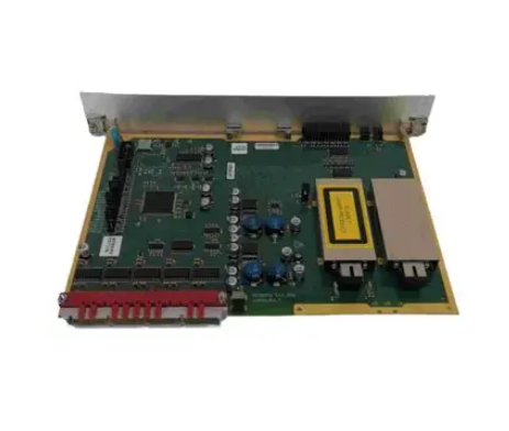
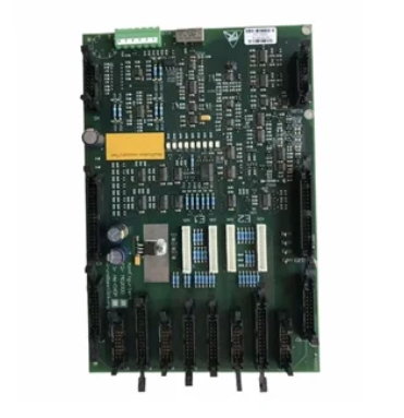
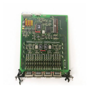
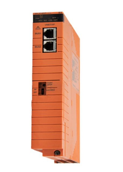
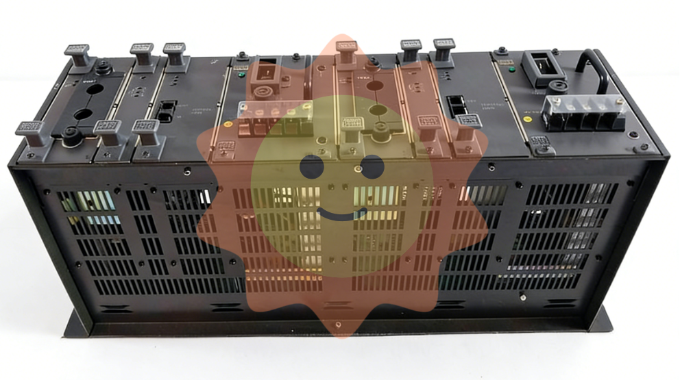
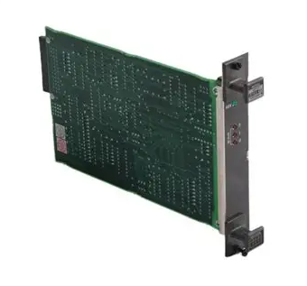
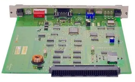
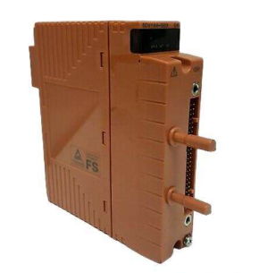
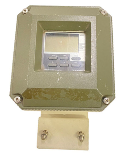
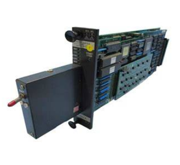
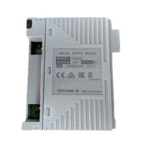
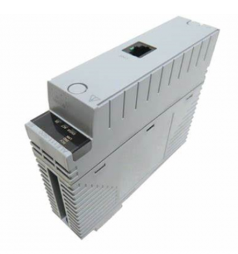
DEIF PPU-3 Parallel and Protection Unit
Stand alone operation: independent power supply control for a single generator;
Parallel with other generators: Multiple generators are synchronized in parallel to achieve load distribution and coordinated control.
Its core value lies in simplifying the generator control chain, which can be connected to the PLC control system through digital/analog I/O or serial communication, and has flexible functional expansion capabilities.
Busbar over/under frequency (81) 3rd/4th order to maintain bus frequency stability
Busbar voltage imbalance (60) 1st order prevention of equipment failure caused by three-phase voltage imbalance
Generator overload (32) 5th order to avoid long-term operation of the generator beyond rated load
Current/Voltage Imbalance (60) 1st order protection for generators and loads from damage caused by unbalanced current/voltage
Overexcitation/Loss of excitation (40/32 RV) 1st order protection generator excitation system to avoid magnetic field anomalies
Hardware and interface specifications
(1) Hardware architecture and slot allocation
The PPU-3 adopts a "slot based" hardware design, with fixed slots corresponding to different functional modules. Each slot only supports one hardware option, and the core slot functions are as follows:
Slot Number Function Category Standard Configuration/Optional Options Core Interface and Parameters
1. Power supply and basic I/O standard 8-36V DC power supply (11W); 1 status output relay; 5 relay outputs; 2 pulse outputs (kWh, kvarh); 5 digit inputs
Communication options include H2 (Modbus RTU/ASCII, RS-485), H3 (Profibus DP), etc., which are responsible for serial communication with external systems such as PLCs
3 load distribution standards with 13 numerical inputs; 4 relay outputs; 1 P (active) load distribution line; 1 Q (reactive power) load distribution line; 2 external set point inputs (GOV/AVR)
4 GOV/AVR/transmitter output standards (4 relay outputs); Optional E1 (2-channel+/-25mA), E2 (2-channel 0 (4) -20mA) and other output control signals can be sent to the speed regulator/AVR, or used as transmitter signal output
5 AC measurement standards, 3 generator voltage inputs; 3-channel generator current input; 3-channel bus/grid voltage input
6 Analog Output Expansion Optional F1 (2-channel 0 (4) -20mA transmitter output) to expand analog output channels
7 engine control and I/O expansion options include M4 (engine control, digital/analog I/O) and H7 (software level engine communication) to achieve engine start stop control, I/O expansion, and specific engine protocol docking
8. Advanced communication and load distribution options include G9 (CANshare), H5 (specific engine protocols such as Caterpillar, MTU), digital load distribution, and engine specific communication protocol docking
9 Ethernet communication options include N (Ethernet TCP/IP, supporting Modbus TCP/IP, EtherNet/IP, SMS/email alarms) to achieve remote monitoring and alarm notification over Ethernet
(2) Key technical parameters
Parameter category specific specifications
Working environment temperature: -25~70 ° C (-25~60 ° C with N option; UL/cUL certified environment maximum 55 ° C); Humidity: 97% RH (IEC 60068-2-30); Altitude: 0-4000m (downgraded for use from 2001 to 4000m)
Measurement range voltage: 100~690V AC (± 20%, UL/cUL certified maximum 600V AC); Current: 1/5A AC (from CT); Frequency: 30~70Hz
Auxiliary power terminal 1-2:12/24V DC nominal (8-36V DC operation, maximum 11W); Terminal 98-99:12/24V DC nominal (8-36V DC operation, maximum 5W); 2A slow melting fuse protection is required
Input/output digital input: optocoupler isolation, 8-36V DC conduction (impedance 4.7k Ω); Analog input: 0 (4) -20mA (impedance 50 Ω) RPM(MPU:2-70V AC,10-10000Hz); Relay output: 250V AC/30V DC (5A, UL/cUL certified 2A resistive load); Analog output: 0 (4) -20mA/± 25mA (isolated, maximum load 500 Ω)
Electrically isolated AC voltage from other I/O: 3250V AC (50Hz, 1min); AC current and other I/O: 2200V AC (50Hz, 1min); Analog output and other I/O: 550V AC (50Hz, 1min)
Protection level host: IP20; Display unit: IP40 (optional L gasket can be upgraded to IP54, required for RS certification applications)
Certified ship certification: certified by all mainstream classification societies; Safety certification: EN 61010-1, UL 508, CSA 22.2 No.14-05; EMC certification: EN 61000-6-2/4, IEC 60255-26
Optional Features and Accessories
(1) Core optional options (some key options)
Specific description of option code function category
A-series power grid protection package A1 (limited time undervoltage 27t, undervoltage+low reactive power 27Q, etc.), A5 (directional overcurrent 67)
C2 Generator Extended Protection Package Negative Sequence Voltage High 47, Negative Sequence Current High 46, Zero Sequence Voltage High 59, etc
D1 Voltage Control Fixed Voltage, Fixed Reactive Power, Fixed Power Factor, Reactive Load Distribution, Voltage Drop
G9 CANshare digital load distribution+line monitoring, multi BTB monitoring, dead bus closing
H2/H3 serial communication H2 (Modbus RTU/ASCII, RS-485), H3 (Profibus DP)
N Ethernet Modbus TCP/IP, EtherNet/IP, SMS/email alerts
Y1/Y11 display and control Y1 (engine and GB control), Y11 (display unit without local control button)
(2) Standard and optional accessories
Accessory type, specific product usage, model/remarks
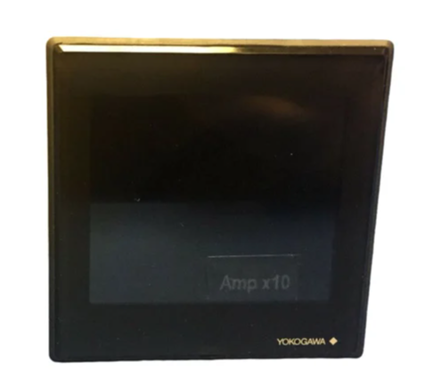
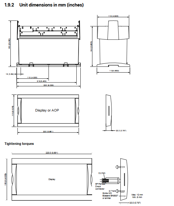
Display Unit DU-2 (Standard): The host is equipped with Display 2912210050, and the display layout needs to be specified
DU-2 (extension) additional extension display 2912890030, supports CAN bus
AOP-1 expansion operation buttons and LED 2912890040 on the operation panel, with a maximum of one unit per display
- EMERSON
- Honeywell
- CTI
- Rolls-Royce
- General Electric
- Woodward
- Yaskawa
- xYCOM
- Motorola
- Siemens
- Rockwell
- ABB
- B&R
- HIMA
- Construction site
- electricity
- Automobile market
- PLC
- DCS
- Motor drivers
- VSD
- Implications
- cement
- CO2
- CEM
- methane
- Artificial intelligence
- Titanic
- Solar energy
- Hydrogen fuel cell
- Hydrogen and fuel cells
- Hydrogen and oxygen fuel cells
- tyre
- Chemical fiber
- dynamo
- corpuscle
- Pulp and paper
- printing
- fossil
- FANUC
- Food and beverage
- Life science
- Sewage treatment
- Personal care
- electricity
- boats
- infrastructure
- Automobile industry
- metallurgy
- Nuclear power generation
- Geothermal power generation
- Water and wastewater
- Infrastructure construction
- Mine hazard
- steel
- papermaking
- Natural gas industry
- Infrastructure construction
- Power and energy
- Rubber and plastic
- Renewable energy
- pharmacy
- mining
- Plastic industry
- Schneider
- Kongsberg
- NI
- Wind energy
- International petroleum
- International new energy network
- gas
- WATLOW
- ProSoft
- SEW
- wind
- ADVANCED
- Reliance
- YOKOGAWA
- TRICONEX
- FOXBORO
- METSO
- MAN
- Advantest
- ADVANCED
- ALSTOM
- Control Wave
- AB
- AMAT
- STUDER
- KONGSBERG
- MOTOROLA
- DANAHER MOTION
- Bently
- Galil
- EATON
- MOLEX
- Triconex
- DEIF
- B&W
- ZYGO
- Aerotech
- DANFOSS
- KOLLMORGEN
- Beijer
- Endress+Hauser
- MOOG
- KB
- Moxa
- Rexroth
- YAMAHA
- Johnson
- Westinghouse
- WAGO
- TOSHIBA
- TEKTRONIX
- BENDER
- BMCM
- SMC


Email:wang@kongjiangauto.com

