
HIMA X-CPU 01 processor module
Can handle up to 32 user programs
Perform all central functions, including communication
Use up to 3 additional processor modules to handle redundancy
Process communication through secure Ethernet.
Create and store CPU events.
Store events created by I/O modules.
HIMA X-CPU 01 processor module
Product description
The data processing within the HIMax system absolutely requires the X-CPU 01 processor module. The processor module is used for:
Can handle up to 32 user programs
Perform all central functions, including communication
Use up to 3 additional processor modules to handle redundancy
Process communication through secure Ethernet.
Create and store CPU events.
Store events created by I/O modules.
This module has obtained T Ü V's safety related application certification, with a maximum of SIL 3 (IEC 61508, IEC 61511, and IEC 62061), Cat. 4 (EN 954-1) and PL e (EN ISO 13849-1).
The security function of the module
The security features of the processor module include the following:
Processing user program. -If a malfunction occurs: Stop the user program and reset the variable to its initial value - If a malfunction occurs: Reset the processor module to a safe state and report to the CPU
status
Use safety related Ethernet protocols for secure communication between HIMA controllers (HIMax, HIMatrix, and remote I/O modules).
The data is transmitted through the Ethernet interface of the processor module itself or the Ethernet interface of the COM module.
Safety functions are executed according to SIL 3.
The following elements also contribute to achieving security features:
Hardware self-test
Secure communication with I/O modules
Reaction when a malfunction occurs
If a fault is detected in the test harness, the processor module will enter the ERROR STOP state and restart. Diagnostic information can be used to investigate the cause of the malfunction.
Start after error stop
If the cause of the malfunction still exists, the processor module will avoid restarting and repeating erroneous stops:
After the first error stop, the processor module restarts normally and switches to its system operation.
After the second error stop, the user must restart the system using PADT after resolving the issue.
Once the processor module runs for approximately one minute in system operation, the next error stop that occurs is considered the first error stop.
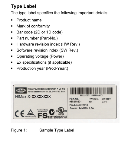
Type label
The type label specifies the following important details:
Product Name
Qualification mark
Barcode (QR code or one-dimensional code)
Part Number (Part Number)
Hardware Revision Index (HW Rev.)
Software Revision Index (SW Rev.)
Working voltage (power)
Explosion proof specifications (if applicable)
Production Year (Production Year:)
Security related processor system
The security related processor module is a 1oo2 processor system. Continuous self inspection ensures safety related operations.
Features:
Two synchronous microprocessors
Specific DDRAM memory for each microprocessor
Testable hardware comparator for data bus
Watchdog (WD)
Gold capacitors for buffering date/time
LED used to indicate system status
Mode switch used to configure module behavior when voltage is turned on
The processor module compares data between two processors and triggers an interrupt if the following conditions occur Fault occurred.
The monitor monitors two processors. The self check of the module will also check the watchdog.
system controller
The entire data transmission between various components of the system controller processing module:
Security related processor system
System bus A and B
Ethernet switch with connection interface
memory
This module has RAM and non-volatile memory. Non volatile memory is protected by CRC.
Non volatile memory contains the following programs and information:
operating system
User project
Enable switch, watchdog time, safety time
Online modification
Variables with RETAIN attribute
Production data, if necessary, trim data
Fault status history
event
At startup, the system transfers program code from non-volatile memory to redundant program and data storage.
Alarm and Events
The processor module records alarms and other events in its non-volatile memory.
An event is a change in the state of a variable executed by a factory or controller, with a timestamp provided.
An alert is an event that indicates an increase in potential risk.
The HIMax system records state changes as events at a specified point in time. The X-OPC server transfers events to other systems that display or evaluate events, such as control systems.
HIMax distinguishes between Boolean events and scalar events.
Boer Event:
The variation of Boolean variables, such as the variation of numerical inputs.
Alarm and normal states: They can be arbitrarily assigned to variable states.
Scalar event:
Exceeding the limit value defined for scalar variables.
Scalar variables have numerical data types, such as INT and REAL.
Two upper limits and two lower limits are possible.
For the limit value, the following conditions must be met:
Maximum limit ≥ upper limit ≥ normal area ≥ lower limit ≥ minimum limit.
Lag may be effective in the following situations: - if the value is below the upper limit. If the value exceeds the lower limit.
Lag is defined as avoiding unnecessary large events when the global variable oscillates strongly near the limit.
Create Event
Both processor modules and certain types of I/O modules are capable of creating events. at
In the following sections, these I/O modules are referred to as SOE modules.
Create events on the processor module
The processor module creates events using global variables and stores them in a buffer, please refer to Chapter 3.4.7. The event is created during the user program cycle.
Create events on the SOE module
The SOE module can create events using input states. The event is created within the SOE module loop.
The SOE module stores events in the intermediate buffer used by the processor module to read them. The intermediate buffer is a part of volatile memory, so if the power is turned off, events will be lost.
Every event that has been read can be overwritten by a new event.
system event
In addition to recording events related to changes in global variables or input signals, the processor and SOE module also create the following types of system events:
Overflow: Due to buffer overflow, some events were not stored. The timestamp of the overflow event corresponds to the timestamp of the event that caused the overflow.
Initialization: The event buffer has been initialized.
Operation mode stop: SOE module changes its operation mode to stop.
Operation mode 'Run': The SOE module changes its operation mode to 'Run'.
Establish communication: Communication between the processor module and SOE module has begun.
Lost Communication: Communication between Processor Module and SOE Module
Terminated.
The system event contains the SRS identifier of the module that caused the event.
state variable
State variables provide the state of scalar events for user programs. Each of the following states is connected to a state variable that can be assigned a BOOL type global variable:
Normal.
Exceeding the lower limit.
The minimum limit has been exceeded.
Exceeding the upper limit.
The maximum limit has been exceeded.
When the corresponding state is reached, the assigned state variable becomes TRUE.
Recording events
Processor module collects events:
Created by I/O module
Created by the processor module itself
The processor module stores all events in its buffer. A buffer is a part of non-volatile memory with a capacity of 5000 events.
The processor module arranges events from different sources based on their arrival time, rather than sorting them by timestamp.
If the event buffer is full, as long as no other events are read and marked as overwritten, new events cannot be stored.
OPC servers can read events and provide them to external systems for evaluation and storage.
Mode Switch
The mode switch defines the behavior of the processor module when it restarts.
The processor module will restart in the following situations:
Automatic: - When connected to working voltage - After severe malfunction - After loading the operating system
During the operation, use the corresponding commands on PADT.
The mode switch has three different switch positions:
initialization
stop
run
The switch position during normal operation is in operation.
Switch position: initialization
The Init switch position is used to set the processor module to LOCKED state. In this state, the settings previously configured for the module cannot be accessed anymore. For example, if the administrator password is unknown, this operation may need to be performed.
In the locked state, the module is reset to factory settings:
Default SRS, slot number depends on the slot used
Default IP address and IP settings
Only administrator user accounts with empty passwords can access
Enable the switch set to default value
The modified settings in this state will overwrite the factory settings and all previously used settings!
If the settings remain unchanged, the previously saved settings (switch not set to Init) will be used when restarting the module.
start
To start the processor module, insert it into the allowed motherboard slot. If the substrate is already running, the processor module will start and adopt the operating state set through its configuration and mode switch position. If the substrate is not working, please connect the power supply voltage.
install
When installing the processor module, please pay attention to the following points:
This module is designed for use with HIMax substrates. For more information about the bottom plate structure, please refer to the corresponding system documentation.
Operate the processor module only in the expected slot
Only the forced cooling (X-FAN) operation module can be used.
Only use appropriate connector boards to operate the module.
The effect of removing and inserting modules:
When disassembling the module, the connector board remains in the HIMax substrate.
Since all external interfaces are connected through the module's connector board, the module can be replaced without affecting the external interfaces
The SRS of the module is stored on the connector board and becomes SRS after the module is inserted.
The effect of removing the plug
Pulling out the plug will interrupt external communication.
Take appropriate grounding measures.
User Program
The application program functions that PES should execute are specified in the user program. PADT is used to create and compile project configurations using user programs, and load them into processor modules.
Start processor module
The processor module can be started as follows:
Insert it into the substrate that provides working voltage
Open the working voltage of the substrate for inserting the module.
The behavior at module startup depends on:
Position of mode switch
There are additional redundant processor modules present
There are valid project configurations (including user programs) in non-volatile memory
When the switch is set to stop or run, the processor module will check if there are any other processor modules present
If there are no other processor modules, the module will start running separately.
If there is at least one additional processor module, the module attempts to automatically start operating using the configuration of the existing processor module. Maintain a safety rope.
- OMRON
- ABB
- General Electric
- EMERSON
- Honeywell
- HIMA
- ALSTOM
- Rolls-Royce
- MOTOROLA
- Rockwell
- Siemens
- Woodward
- YOKOGAWA
- FOXBORO
- KOLLMORGEN
- MOOG
- KB
- YAMAHA
- BENDER
- TEKTRONIX
- Westinghouse
- AMAT
- AB
- XYCOM
- Yaskawa
- B&R
- Schneider
- KONGSBERG
- NI
- WATLOW
- ProSoft
- SEW
- ADVANCED
- Reliance
- TRICONEX
- METSO
- MAN
- Advantest
- STUDER
- DANAHER MOTION
- Bently
- Galil
- EATON
- MOLEX
- DEIF
- B&W
- ZYGO
- Aerotech
- DANFOSS
- Beijer
- Moxa
- Rexroth
- Johnson
- WAGO
- TOSHIBA
- BMCM
- SMC
- HITACHI
- HIRSCHMANN
- Application field
- XP POWER
- CTI
- TRICON
- STOBER
- Thinklogical
- Horner Automation
- Meggitt
- Fanuc
- Baldor
- SHINKAWA
- Other Brands
- UniOP
- KUKA
- Iba
- Beckhoff
-
 Basler D90 96801 100 PCB Card
 -
 Basler XR2002F Voltage Regulator (110 VAC, 48-480 Hz)
 -
 Basler SR8A-2B14B3A Regulator
 -
 Basler 9561500100 Module
 -
 Basler DECS-400 BE1-11 System
 -
 Basler DECS-100-B15 Excitation Control
 -
 Basler SCP 210 Frequency Controller
 -
 Basler SR4A-2B15B3A Static Voltage Regulator
 -
 Basler BE1-32R Power Relay
 -
 Basler PIA2400-17GM Power Interface Adapter
 -
 Basler MVC 232 Manual Voltage Control Module
 -
 Basler SSR 32-12 Static Voltage Regulator
 -
 Basler 5MW AVR Generator Voltage Regulator
 -
 Basler VR63-4B Voltage Regulator
 -
 Basler DECS-100-A05 AVR for Engine Generator
 -
 Basler DECS-100-B15 Automatic Voltage Regulator
 -
 Basler BE1-32R Directional Power Relay
 -
 Basler BE1-87B Differential Relay
 -
 Basler UFOV 260A Protective Module
 -
 Basler 9-2614-02-100 PCB Rev M
 -
Basler DECS-100-B15 Digital AVR
-
 Basler 9284900103 PS DECS-400N
 -
 Basler D4N3H1U Intertie Protection
 -
 Basler DECS-100-B15 A15 AVR
 -
 Basler KR4F Voltage Regulator
 -
 Basler BE26434 T14 Transformer
 -
 Basler SR8A-2B15B3A Regulator
 -
 Westinghouse 774B472A12 AR Relay
 -
Basler DECS-100-B15 AVR
-
Basler XR2002F Regulator 110V
-
Basler SR125-E Static Regulator
-
 Basler SSR 125-12 Regulator
 -
 Basler MOC2599 Motor Pot
 -
 Basler BE1-DFPR Feeder Relay
 -
 Basler CBS 305 Current Boost
 -
 Basler BE1-25 AutoSync
 -
 Basler MVC 300 Voltage Control
 -
 Basler BE3-25A AutoSync
 -
 Basler KR7FF Static Regulator
 -
 Basler 90-49000-100 Regulator
 -
 Basler 880 kVA Dry Type Transformer Specs
 -
 Basler Electric BE1-25 Sync-Check Relay Specs
 -
 Basler SSR 125-12 Voltage Regulator Specs
 -
 Basler Electric BE1-851 Overcurrent Relay Review
 -
Basler Electric 149D930G02 Control Sub-Assembly
-
 Basler Electric BE1-81O/UT Frequency Relay Specs
 -
 Basler Electric BE1-51/27C Overcurrent Relay
 -
 Basler Electric 149D956G02 Industrial Component
 -
Basler Electric BE1-51A Overcurrent Relay Specs
-
 Basler Electric BE1-40Q Loss of Excitation Relay
 -
 Basler DECS-200 Excitation Control System
 -
 Basler DECS-200 Voltage Regulator 56-277V AC / 125V DC
 -
Basler BE1-87T Transformer Differential Relay
-
 Basler RDP-110-S1 Protection Relay
 -
 Basler BE1-700V Digital Protective Relay
 -
 Basler BE1-951 Overcurrent Protection System
 -
 Basler DECS-300 Digital Excitation Control
 -
 Basler DECS-200 Digital Excitation Control
 -
 Basler DECS-200-1C Excitation Control System
 -
Basler DECS-200-1L Digital Excitation Control
-
 Basler Electric BE1-GPS Generator Protection System
 -
Basler Electric DECS-200-1C Digital Excitation Controller
-
 Basler Electric DECS125-15 Excitation Control with Power Module
 -
 Basler Electric BE1-87G Differential Relay
 -
 Basler Electric BE1-11 Protection System I5A3M2P2N0EA00
 -
Basler Electric DECS-200-1C Excitation Control System
-
Basler Electric BE1-11g Generator Protection Relay
-
Basler Electric DECS 125-15-B2C1 V2.0.9 Excitation Control
-
 Basler Electric BE1-81O/UT3ED1JA7N2F Frequency Relay
 -
Basler Electric BE1-81O/UT3EE1YB7N1F Frequency Relay
-
 Basler Electric DECS-200-1L Digital Excitation Control System
 -
Basler DECS125-15-B2C1 Excitation Control
-
 Basler 9507900205 SSR Retrofit Voltage Regulator
 -
 Basler BE2000E Digital Voltage Regulator
 -
 Basler BE1-GPS Generator Protection System
 -
Basler DECS-250-CN1CN1N Digital Excitation Control
-
 Basler DGC-2020 Genset Controller
 -
 Basler BE1-81O UT3ED1LA7N0F Frequency Relay (Variant)
 -
 Basler BE1-81O UT3EE1YA9S0F Frequency Relay (Variant)
 -
Basler BE1-81O Over/Under Frequency Relay
-
Basler DECS125-15 Digital Excitation Control
-
Basler Electric BE1-951 Overcurrent Protection System
-
 Basler Electric BE1-700V Digital Protective Relay
 -
 Basler Electric APR63-5 Automatic Voltage Regulator
 -
Basler Electric BE1-851 Overcurrent Protection System
-
Basler Electric DECS-250-LN1SN1N Excitation Control
-
 Basler Electric BE1-87T Transformer Differential Relay
 -
Basler Electric DECS-200-1L Excitation Control System
-
 Basler Electric 9310300100 DECS-300 Excitation Control
 -
 Basler Electric SSE-N 125-4.5KW Shunt Exciter Regulator
 -
 Basler Electric DGC-2020HD-5NS1DNSBA Genset Controller
 -
Basler Electric BE1-81-O/UT3EE1JB7N1F Frequency Relay
-
Basler Electric BE1-81T1EE1WA0N1F Frequency Relay
-
 Basler Electric BE1-25M1EA6PN5R1F Sync-Check Relay
 -
 Basler Electric BE1-GPS Generator Protection System
 -
Basler Electric DECS-250-LN1SN1N Excitation Control Rev V
-
 Basler Electric DECS-250-CN2CN1N Excitation Control
 -
Basler Electric BE1-50/51B-207 Overcurrent Relay
-
Basler Electric DECS-300-C0N0 Excitation Control System
-
Basler Electric DECS-200 Digital Excitation Control System
-
Basler Electric DECS-250-LN1CN1N Excitation Unit
-
Basler Electric DECS-250 LN2SA1D Excitation Unit Specs
-
Basler Electric BE1-87T Transformer Relay Review
-
Basler Electric BE1-11 Protection System
-
Basler Electric BE1-GPS100-E4N1H1N Protection System
-
 Allen-Bradley 442G-MABH-R Safety Module
 -
 Beckhoff CX1030-0111 PLC Assembly Profile
 -
 FANUC IC693CPU364 PLC Module
 -
 Orange Denmark Type 200816 220 PLC Specs
 -
 OMRON C200H-SNT31 Sysmac PLC Module
 -
 Allen Bradley 20AB022A3AYNANC0 PowerFlex 70
 -
 OMRON C200HW-PCU01 Position Control Unit
 -
 ABB AO845A-eA Analog Output Module
 -
 OMRON CJ1M-CPU22 CPU Unit
 -
 Allen Bradley 100-E265ED11 Contactor
 -
 Honeywell 51304511-100 Interface Module
 -
 SOLEXY BXF3S0101N0018 Gateway Module
 -
 OMRON CJ2H-CPU65 CPU Unit
 -
 Automation Direct GS2-45P0 AC Drive
 -
 M68-2000 2-Axis Motion CNC Controller
 -
 OMRON CJ1M-CPU11 V3.0 PLC CPU Unit
 -
 OMRON CJ1W-NC413 4-Axis Positioning Controller
 -
 OMRON 3G2A3-PRO16 Programming Console HMI
 -
 Siemens 3VT8440-2AA04-2GA2 Molded Case Circuit Breaker
 -
 Siemens 3RT5045 Contactor Series
 -
 OMRON C200HS-CPU01-E SYSMAC PLC Controller
 -
 OMRON C500-NC103-E Positioning Control Unit
 -
 OMRON CJ1W-TC001 Temperature Control Unit


