
ABB Sace BSD series brushless servo drive
ABB Sace BSD series brushless servo drive
Equipment Overview
1. Specification of servo amplifier
Model Applicable Motor Capacity Power Type Key Parameters
BSD0100 BSM0100 (100W) single-phase 200-230V carrier frequency 10kHz, overload capacity 300%/about 3 seconds
BSD0200 BSM0200 (200W) single-phase 200-230V-
BSD0400 BSM0400 (400W) single-phase 200-230V-
BSD0750 BSM0750 (750W) single-phase/three-phase 200-230V-
BSD1000 BSM1000 (1000W) three-phase 200-230V-
BSD1500 BSM1500 (1500W) three-phase 200-230V-
BSD2000 BSM2000 (2000W) three-phase 200-230V-
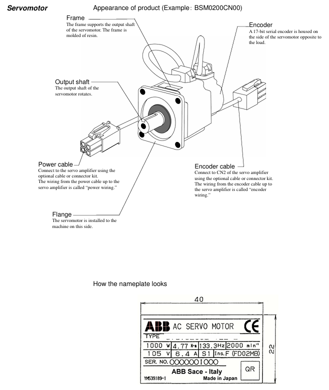
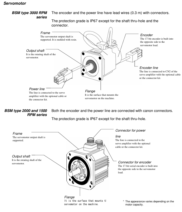
2. Specification of servo motor
Series model Capacity Rated speed Rated torque Encoder
Low inertia BSM0100 100W 3000r/min 0.318N · m 17 bit serial
Low inertia BSM0200 200W 3000r/min 0.637N · m 17 bit serial
Low inertia BSM0400 400W 3000r/min 1.27N · m 17 bit serial
Low inertia BSM0750 750W 3000r/min 2.39N · m 17 bit serial
Medium inertia BSM1000 1000W 2000r/min 4.77N · m 17 bit serial
Medium inertia BSM1500 1500W 2000r/min 7.16N · m 17 bit serial
Medium inertia BSM2000 2000W 2000r/min 9.55N · m 17 bit serial
3. Model coding rules
Servo amplifier: Only specify power, such as the power corresponding to "XXXX" in "BSDXXXX" (0100=100W).
Servo motor: format is "BSMXXXXXX", where "XXXX"=power, "C"=shaft type (C=keyway, L=flat shaft), "N/B"=brake (N=none, B=present), "00/01"=option (00=none, 01=oil seal).
Installation requirements
1. Installation of servo motor
Project Requirements Remarks
Storage environment temperature -20 ° C~60 ° C, humidity 10% -90% RH (no condensation), the same requirement applies when equipped with gear heads
Working environment temperature -10 ° C~40 ° C, humidity 10% -90% RH (no condensation), temperature with gear head 0 ° C~40 ° C
The installation direction can be horizontal, downward, or upward (in accordance with IEC standards IMB5/L51, etc.), and the encoder end should not be subjected to force
Load limit radial load (127N-510N), axial load (19N-253N) refer to Table 2-5 in the document, such as BSM0100 radial 127N
Cable protection for mobile scenarios requires drag chains with a maximum bending radius to avoid oil/water immersion
2. Installation of servo amplifier
Project Requirements Remarks
Storage environment temperature -20 ° C~85 ° C, humidity 10% -90% RH (no condensation), altitude ≤ 1000m, no dust/corrosive gas
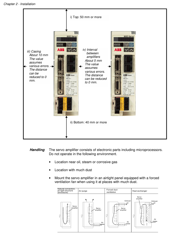
Working environment temperature -10 ° C~55 ° C, humidity 10% -90% RH (no condensation), non drip/dust-proof, multiple installations require spacing
Installation direction Upright direction (horizontal marked with "BSD") Heat dissipation requirements
When the installation spacing is ≥ 50mm at the top and ≥ 40mm at the bottom, and the spacing between multiple parallel units is ≥ 5mm and < 5mm, the rating needs to be reduced to 80% ED
Leave ≥ 70mm (for easy operation) for wiring in the front space, with a depth of 165mm for 1.0kW and below, and 185mm for 1.5kW and above
Wiring specifications
1. Power wiring
Equipment power type, wiring terminal voltage range, frequency
Servo amplifier (0.4kW and below) single-phase L1, L2 200-230VAC (-10%~+10%) 50/60Hz
Servo amplifier (0.75kW) single-phase/three-phase L1, L2 (single-phase); L1, L2, L3 (three-phase) 200-230VAC (single-phase -10%~+10%, three-phase -15%~+10%) 50/60Hz
Servo amplifier (0.85kW and above) three-phase L1, L2, L3 200-230VAC (-15%~+10%) 50/60Hz
Control power supply (all models) single-phase sL1, sL2 200-230VAC (-10%~+10%) 50/60Hz
2. Key wiring taboos
Do not connect the commercial power supply (200V) to the U/V/W terminals of the servo motor (as it may burn the motor).
Do not connect the grounding wire (E) to the U/V/W terminal, and do not connect the U/V/W terminal in reverse (which may cause fire/malfunction).
It is prohibited to conduct voltage withstand, megaohm, and buzzing tests on the encoder terminal (CN2) as it may damage the encoder.
The distance between the serial I/O (CN1) and the motor power cable should be ≥ 10cm (to avoid interference).
Test Run
1. Three stage testing process
Key inspection items for stage testing content
The first stage servo amplifier and motor are tested separately (not connected to the machine). 1. Power wiring (L1/L2/L3); 2. Motor power supply (U/V/W) and encoder wiring; 3. Motor rotation direction (parameter # 04); 4. No alarm
In the second stage, connect to the upper control system (not connected to the machine). 1. Connect the signal lines of the upper system; 2. I/O signals (such as emergency stop EMG, overtravel ± OT); 3. Motor speed/torque (in accordance with instructions)
The third stage of testing after installing the machine (final state): 1. The firmness of the motor installation; 2. Machine travel; 3. Servo parameter adjustment (refer to Chapter 6); 4. Positioning accuracy
2. Origin regression requirements
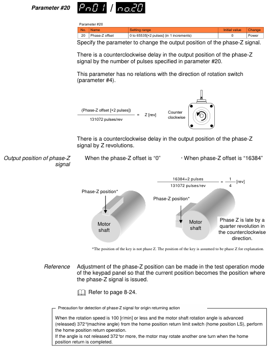
After power failure and restart, the motor needs to be rotated at a speed of ≤ 100r/min for 372 ° or more (approximately 1.04 rpm) in order to correctly detect the Z-phase.
Parameter settings
1. Parameter configuration method
Keyboard operation: Switch to "Parameter Editing Mode" (PnO) for settings through a 4-digit 7-segment LED display and 4 buttons (MODE/ESC, SHIFT, ENT, ∧/∨).
BSD Configurator: Connected to CN3 via LAN cable (CAT. 5 direct connection), supports parameter read/write, batch transfer, and monitoring.
2. Core parameter table
Parameter number, parameter name, control mode, setting range, initial value, key role
#01 Command pulse compensation alpha position 1-32767 16 electronic gear ratio molecule, converting command pulse to mechanical stroke
#02 instruction pulse compensation β position 1-32767 1 electronic gear ratio denominator
#03 Pulse train input form: Position 0 (command pulse+symbol), 1 (forward/reverse pulse), 2 (two signals with a 90 ° phase difference), 1 matches the output type of the upper system pulse
#04 Rotation direction switching/output pulse phase all 0-30 set motor forward rotation direction (CCW/CW) and output pulse phase
#05 tuning mode position/speed 0 (automatic), 1 (semi-automatic), 2 (manual) 0 select servo gain tuning mode
#06 Load inertia ratio position/velocity GYS: 0.0-100.0; GYG: 0.0-30.0 5.0 (BSM low power), 1.0 (BSM high power) ratio of motor inertia to load inertia
#07 Automatic tuning gain position/speed 1-20 10 Adjust servo response speed (high value, fast response but prone to vibration)
#09 Control mode switch all 0 (position), 1 (speed), 2 (torque), 3 (position) ↔ 0 fixed or switchable control mode for speed)
3. Parameter Effectiveness Rules
The parameters marked as "Power" (such as # 03, # 04, # 09) need to be powered off and restarted to take effect; Other parameters (such as # 01, # 02, # 07) take effect in real-time.
Servo adjustment and special functions
1. Tuning method
Operation points for applicable scenarios of tuning types
Automatic tuning (# 05=0) Most conventional mechanical amplifiers automatically estimate the inertia ratio and set the optimal gain
Semi automatic tuning (# 05=1) inaccurate estimation of inertia ratio, manual setting of # 06 (load inertia ratio) in scenarios, amplifier automatically calculates gain
Manual tuning (# 05=2) Automatic/semi-automatic tuning failed. Manually set # 40 (position gain), # 41 (speed response), # 42 (speed integration time), etc
2. Special adjustment function
Vibration suppression control: By setting parameters # 60- # 63 (anti resonance frequency 0-3), mechanical vibrations (such as end effector vibrations of robotic arms) are suppressed within a frequency range of 5.0-200.0Hz.
Instruction Follow Control: Parameter # 55 is set (0=none, 1=follow, 2=follow+stop compensation) to achieve zero deviation following of pulse instructions, suitable for high rigidity machinery.
Inspection and maintenance
1. Regular inspection items
Equipment inspection content inspection frequency
Servo motor 1. Mechanical coupling deviation; 2. Smoothness of axis rotation; 3. Cable damage; 4. Loosening of screws regularly (e.g. monthly)
Servo amplifier 1. Dust accumulation; 2. Abnormal noise from the cooling fan; 3. Loose terminal screws; 4. No odor/signs of overheating regularly (e.g. monthly)
2. Service life and replacement of vulnerable parts
Component Standard Life Replacement Tips
Servo amplifier main circuit capacitor 73000h (10 years), lifespan shortened when ambient temperature exceeds 30 ° C
Replace the servo amplifier cooling fan when it makes abnormal noise or stops running after 30000 hours (3 years)
Replace servo motor bearings when vibration/abnormal noise occurs after 20000-30000 hours (3-5 years)
Replace the servo motor oil seal after 5000 hours of oil leakage
3. Common alarm handling
Alarm code, alarm reason, handling measures
OC1/OC2 overcurrent 1. Check the U/V/W wiring of the motor; 2. Check if the motor is short circuited/grounded; 3. Replace the amplifier
OL overload 1. Check motor load matching; 2. Extend the acceleration and deceleration time; 3. Reduce operating frequency
HV overvoltage 1. Check the power supply voltage; 2. Connect external regenerative resistors; 3. Extend deceleration time
LV undervoltage 1. Check the power supply voltage; 2. Confirm parameter # 26 (undervoltage detection) setting; 3. Improve the power environment
RS485 communication
1. Communication specifications
Project specifications
Signal level RS485
Communication method: 4-wire half duplex, asynchronous communication
Baud rate 9600/19200/38400bps (parameter # 83 setting)
Data format: 1 start bit, 8 data bits, 1 even check bit, 1 stop bit
Station number 1-31 (parameter # 2 setting)
Connect cable LAN line (CAT. 5 direct connection)
2. Core functions
Read: Multiple monitoring data (such as speed, torque), sequence mode, I/O signals, alarm history, system status.
Write: parameters, alarm reset, parameter initialization.
Key issue
Question 1: What are the matching rules between BSD series servo amplifiers and servo motors? What are the differences in power wiring requirements for amplifiers of different capacities?
Answer:
Matching rule: The selection should be based on the principle of "consistent capacity+matching speed", and the specific corresponding relationship is shown in the table below:
Servo amplifier model applicable servo motor model motor capacity motor rated speed
BSD0100 BSM0100xxxx 100W 3000r/min
BSD0200 BSM0200xxxx 200W 3000r/min
BSD0400 BSM0400xxxx 400W 3000r/min
BSD0750 BSM0750xxxx 750W 3000r/min
BSD1000 BSM1000xxxx 1000W 2000r/min
BSD1500 BSM1500xxxx 1500W 2000r/min
BSD2000 BSM2000xxxx 2000W 2000r/min
(Note: "xxxx" represents motor shaft type, brake and options, such as BSM0100CN00=100W, keyway shaft, no brake, no options)
Differences in power wiring:
0.4kW and below (BSD0100/0200/0400): Only supports single-phase 200-230VAC, wired to L1 and L2 terminals, voltage fluctuation allowed -10%~+10%.
0.75kW (BSD0750): Supports single-phase or three-phase 200-230VAC, with single-phase connected to L1 and L2, and three-phase connected to L1, L2, and L3; Single phase voltage fluctuation -10%~+10%, three-phase -15%~+10%.
0.85kW and above (BSD1000/1500/2000): Only supports three-phase 200-230VAC, wired to terminals L1, L2, and L3, with allowable voltage fluctuations of -15% to+10%.
All models of control power supply are unified as single-phase 200-230VAC, wired to sL1 and sL2 terminals, with voltage fluctuations ranging from -10% to+10%.
Question 2: What are the core objectives and key operational steps of the three-stage testing in the testing operation of BSD series servo systems? What are the requirements to pay attention to when returning to the origin?
Answer:
Core purpose and steps of three-stage testing:
Key operational steps for the core objectives of the stage
In the first stage, verify that the servo amplifier and motor work separately and eliminate basic wiring/hardware faults. 1. Fix the motor (axis without load); 2. Connect the amplifier motor power/encoder cable (not connected to CN1); 3. Power on and check the charging LED and keyboard display; 4. Test the rotation direction of the motor (parameter # 04) and ensure there are no alarms
The communication and command response between the second stage verification and the upper control system are normal. 1. Connect amplifier CN1 to the upper system; 2. Check the I/O signals (emergency stop EMG, overtravel ± OT, brake timing); 3. Power on and output pulse/analog commands, check motor speed, rotation direction, and I/O signal recognition
The third stage verifies that the motor operates normally as a whole after installation and meets the actual working conditions. 1. Securely install the motor onto the machine; 2. Reproduce the second stage I/O signal inspection; 3. Verify that the machine travel matches the instructions; 4. Adjust servo parameters (refer to Chapter 6) to ensure positioning accuracy/no vibration
Origin regression requirements:
After power failure and restart, the motor needs to rotate 372 ° or more at a speed of * * ≤ 100r/min (approximately 1.04 revolutions, motor output shaft angle) in order to correctly detect the encoder Z phase.
If the requirements of "speed ≤ 100r/min+rotation ≥ 372 °" are not met, the Z-phase cannot be correctly identified, which may result in the motor rotating an additional circle after returning to the origin.
Question 3: In the BSD series servo system, what scenarios are the three settings (automatic/semi-automatic/manual) of core parameter # 05 (tuning mode) applicable to? How to suppress mechanical vibration through parameter adjustment?
Answer:
Tuning mode (parameter # 05) Applicable scenarios:
Tuning mode parameter # 05 setting applicable scenario operation points
Automatic tuning: Most conventional mechanical amplifiers (with stable load inertia and no special resonance) automatically estimate the load inertia ratio without manually setting # 06, directly generating the optimal gain (such as # 40/# 41/# 42)
Semi automatic tuning 1. Inaccurate load inertia estimation scenarios (such as large load fluctuations, high friction, and applications with thrust) 1. Manually set # 06 (load inertia ratio, read or calculated through keyboard monitoring mode); 2. The amplifier automatically calculates gain based on # 06
Manual tuning 2 automatic/semi-automatic tuning failure scenarios (such as obvious mechanical resonance and high rigidity requirements) 1. Manually set # 40 (position controller gain), # 41 (velocity response), and # 42 (velocity integration time); 2. Optimize with # 45 (feedforward filtering) and # 46 (torque filtering); 3. Use BSD Configurator to monitor waveforms
Parameter adjustment method for suppressing mechanical vibration:
Method 1: Enable vibration suppression control (position control only):
First, optimize the servo gain according to Chapter 6 "Basic Adjustment" (ensuring no basic vibration);
Find the mechanical anti resonance frequency (5.0-200.0Hz) through the BSD Configurator servo analysis function;
Set the anti resonance frequency to parameter # 60- # 63 (anti resonance frequency 0-3), while setting # 43 (S-curve time constant, reference: anti resonance frequency<10Hz set 10ms, 10-20Hz set 5ms,>20Hz set 2-3ms).
Method 2: Use notch filter (position/velocity control):
Find the mechanical resonance frequency (through servo analysis function);
Set parameter # 56 (notch filter 1 frequency)=resonance frequency, # 57 (notch filter 1 damping)=5-20dB (to avoid excessive control instability);
If there are two resonance points, repeat step 2 to set # 58 (filter 2 frequency) and # 59 (filter 2 damping).
Method 3: Adjust gain and filtering:
Reduce # 07 (automatic tuning gain) by 1-2 levels (decrease response speed, suppress vibration);
Increase # 46 (torque filtering time constant) by 0.01-0.05ms (smooth torque command, reduce mechanical impact).
- OMRON
- ABB
- General Electric
- EMERSON
- Honeywell
- HIMA
- ALSTOM
- Rolls-Royce
- MOTOROLA
- Rockwell
- Siemens
- Woodward
- YOKOGAWA
- FOXBORO
- KOLLMORGEN
- MOOG
- KB
- YAMAHA
- BENDER
- TEKTRONIX
- Westinghouse
- AMAT
- AB
- XYCOM
- Yaskawa
- B&R
- Schneider
- KONGSBERG
- NI
- WATLOW
- ProSoft
- SEW
- ADVANCED
- Reliance
- TRICONEX
- METSO
- MAN
- Advantest
- STUDER
- DANAHER MOTION
- Bently
- Galil
- EATON
- MOLEX
- DEIF
- B&W
- ZYGO
- Aerotech
- DANFOSS
- Beijer
- Moxa
- Rexroth
- Johnson
- WAGO
- TOSHIBA
- BMCM
- SMC
- HITACHI
- HIRSCHMANN
- Application field
- XP POWER
- CTI
- TRICON
- STOBER
- Thinklogical
- Horner Automation
- Meggitt
- Fanuc
- Baldor
- SHINKAWA
- Other Brands
- UniOP
- KUKA
- Iba
- Beckhoff
-
 Basler SR32A2B05B3E Static Voltage Regulator
 -
 Basler Electric BE1-59N Ground Fault Overvoltage Relay
 -
 Basler Electric 9110000113 Excitation Module
 -
 Basler Electric 90-72300-114 Control Accessory
 -
 Basler Electric PRS-250 Protection Relay System
 -
Basler Electric BE1-50/51M-109 Overcurrent Relay
-
 Basler Electric SR4A1B10B3E Static Voltage Regulator
 -
 Basler Electric CBS 212 Current Boost System
 -
Basler Electric SR32A2B05B3E Static Voltage Regulator
-
Basler Electric MOC2207 Motor Operated Potentiometer
-
 Basler Electric SR4A1B05A3E Static Voltage Regulator
 -
 Basler Electric BE1-32R Power Relay B2EE1PA0N1F
 -
Basler BEI-81 Underfrequency Relay
-
Basler CBS 212A Current Boost System
-
 Basler SSR 63-12 Static Voltage Regulator
 -
 Basler DGC-2020 Digital Genset Controller
 -
Basler BE1-32 Reverse Power Relay
-
 Basler BE1-50/51B-207 Overcurrent Relay
 -
 Basler BE1-951 Overcurrent Protection System
 -
 Basler 9073800-103 Power Supply
 -
 Basler SCA1300-32FC CCD Camera
 -
Basler 9073800-103 Power Supply
-
Basler SCA1300-32FC CCD Camera
-
 Basler L304KC Protective Relay
 -
 Basler BE3-25-1S1N4 Time Overcurrent Relay
 -
 Basler 9032300113 Excitation Support System
 -
 Basler BE1-59N Ground Overvoltage Relay
 -
 Basler MVC-300 Manual Voltage Control Unit
 -
 Basler MOC2102 Potentiometer
 -
 Basler BE1-87G Generator Differential Relay
 -
 Basler Electric DECS-200 Digital Excitation Control System
 -
Basler Electric DECS 125-15-B2C5 Digital Excitation System
-
 Basler Electric PLA2400-12GM Power Supply
 -
 Basler Electric BE1-50/51B-235 Overcurrent Relay
 -
Basler Electric BE1-27/59 Undervoltage Overvoltage Relay
-
 Basler Electric CEM-2020 Contact Expansion Module
 -
 Basler Electric BE1-32R Solid State Power Relay
 -
 Basler Electric BE1-700 Digital Generator Management Relay
 -
Basler Electric BE1-59N Ground Fault Overvoltage Relay
-
 Basler Electric BE10493002 Protection Module
 -
 Basler Electric BEI-79A1AA5CA3M1F Digital Annunciator
 -
 Basler Electric SSR 32-12 Static Voltage Regulator
 -
Basler Electric BE1-CDS240 Current Differential System
-
Basler Electric BE1-67 Directional Overcurrent Relay
-
 Basler Electric 9121000106 DECS-100 Voltage Controller
 -
Basler Electric BEI-871 Interface Module
-
 Basler Electric 8650C72 Exciter Control Module
 -
 Basler Electric RDP-110-S1 Generator Annunciator
 -
Basler Electric BE1-32O/U Directional Power Relay
-
 Basler Electric BE2000E AVR Voltage Regulator
 -
BASLER ELECTRIC BE1-50F2EA1PA0N0F Instantaneous Overcurrent Relay
-
BASLER ELECTRIC BE1-81T1EE1WA0N1F Underfrequency Relay
-
Basler BE1-67 Directional Overcurrent Relay
-
Basler BE1-25/79TR Reclosing Relay
-
Basler CEM-2020 Contact Expansion Module
-
Basler BE1-11 Overcurrent Protection Relay
-
 Basler BE1-GPS Generator Protective Relay
 -
 BASLER ELECTRIC MVC-300 MANUAL VOLTAGE CONTROL UNIT 9121000106
 -
 Basler Electric KR2FF Voltage Regulator 9 1163 00 109
 -
 BASLER ELECTRIC BE1-87G-G1E-A1K-A0N0F Generator Differential Relay
 -
 Basler BE1-47NE3EA1PA0N2F Phase Sequence Relay
 -
 Basler BE1-81-T1E-E1C-B0N1F Frequency Relay
 -
Basler DECS125-15 Excitation Control
-
Basler BE1-25 Sync-Check Relay
-
 Basler BE1-50/51B Overcurrent Relay
 -
Basler BE1-40Q Loss of Excitation Relay
-
 Basler BE1-50/51M-104 Overcurrent Relay
 -
Basler SSE-N 250-9 KW Shunt Exciter Assembly
-
Basler BE1-87T Transformer Differential Relay
-
 Basler BE1-60 Solid State Protective Relay
 -
Basler DECS125-15 Excitation Control System
-
Basler SR4A-2B15B3A Static Voltage Regulator
-
 Basler BE150BF Overcurrent Relay
 -
 BASLER ELECTRIC BE1A1HF1JD1S2F Overcurrent Relay
 -
Basler BE1-81O Under/Over Frequency Relay
-
 Basler EDM-200 Exciter Diode Monitor
 -
 Basler DECS125-15-B2C5 Excitation Control
 -
 Basler 9261402100 PCB Board
 -
Basler 9252000107 Overcurrent Relay
-
Basler BE1-87T Solid State Protective Relay
-
Basler Electric Phase Directional Overcurrent Relay BE1-Z2JA0N2F
-
 Basler SSR125-12 Static Voltage Regulator
 -
 Basler Electric KR7F VOLTAGE REGULATOR 9116200100
 -
BASLER ELECTRIC BE1-59N-A8E-E1L-N0S1F Ground Overvoltage Relay
-
 Basler SR8A2B06B3A Static Voltage Regulator
 -
BASLER ELECTRIC BE1-81O/UT3EE1KA7N1F Under/Over Frequency Relay
-
 Basler MOC2107 Output Module
 -
 Basler 9125600102 Control Module
 -
 BASLER ELECTRIC BE1-81T1EE1EA2N0F
 -
 Basler BE3-25A Time Overcurrent Relay
 -
Basler Electric CBS 212 Current Boost System 9 2650 00 100 120/240 VAC 50/60Hz
-
Basler Electric BE1-27 Under Voltage Relay A3EC1JA0N5F
-
 Basler BE1-32R Power Relay B2EE1PA0N1F
 -
 Basler DECS100-B15 Automatic Voltage Regulator
 -
 Basler SR8A-2B15B3A Static Voltage Regulator
 -
 Basler AVC63-4 Analog Voltage Regulator
 -
 Basler UFOV 260 A Overvoltage Module
 -
 Basler SR4A-2B16B3A Static Voltage Regulator
 -
Basler SR4A-2B16B3E Static Voltage Regulator
-
Basler SCA1300-32GM CCD Camera
-
 Basler BE34062001 G18 Transformer
 -
Basler BE1-87T Transformer Differential Relay
-
 Basler 9 2849 00 101 DECS Power Module
 -
 Basler RAL6144-16GM Line Scan Camera
 -
 Basler 9269101107 Voltage Regulator Board
 -
Basler BE1-851 Overcurrent Relay
-
Basler SR32A-2B13B3E Static Voltage Regulator
-
 Basler 9 2007 00 100 Current Boost System CBS 305
 -
Basler DECS-100-B11 Automatic Voltage Regulator
-
 Basler BE127 Under Voltage Relay
 -
 Basler 3300C03B1028-G01 Spike Suppressor
 -
Basler SSR 125-12 Static Voltage Regulator
-
Basler SCA1300-32GM CCD Camera Lens Enclosure
-
 Basler BE32965001 Transformer Timer Kit
 -
Basler D90 96801 100 PCB Card
-
 Basler BE1-81-T1E-E1C-A0N1F / 9106400 Underfrequency Relay
 -
 Pro-Face Basler AGP3600-T1-D24 HMI Touch
 -
Basler SR4A2B10B1A Static Voltage Regulator
-
Basler SR8A2B05B3A Static Voltage Regulator
-
Basler BE1-25 Time Overcurrent Relay M1FA6PA4S0F
-
Basler SR4A2B05B3E Static Voltage Regulator
-
 Basler DECS-200-2L Digital Excitation Control
 -
 Basler BE303280001 Control Transformer
 -
Basler 9262103004 Voltage Regulator Board For Basler DECS-400
-
 Basler ICRM-7 Inrush Current Reduction Module
 -
Basler BE1-32R Power Relay
-
BASLER ELECTRIC KR4F VOLTAGE REGULATOR 9042600100 600V 50/60Hz
-
Basler 9222600101 Power Module


